Note: This item is only sent to SF Express to pay!
BH1417 is an FM wireless transmitter chip. It can work in the 87MHz~108MHz frequency band. It can be used with simple peripheral circuits to transmit audio FM signals. It can connect computer sound cards, game consoles, CD, DVD, MP3, audio mixers and other stereo The audio signal is transmitted and transmitted in stereo modulation, and can be used with an ordinary FM stereo receiver to realize wireless FM stereo transmission. It is suitable for the production of wireless audio adapters for stereo wireless speakers, wireless headphones, CD, MP3, DVD, PAD, notebook computers, etc.
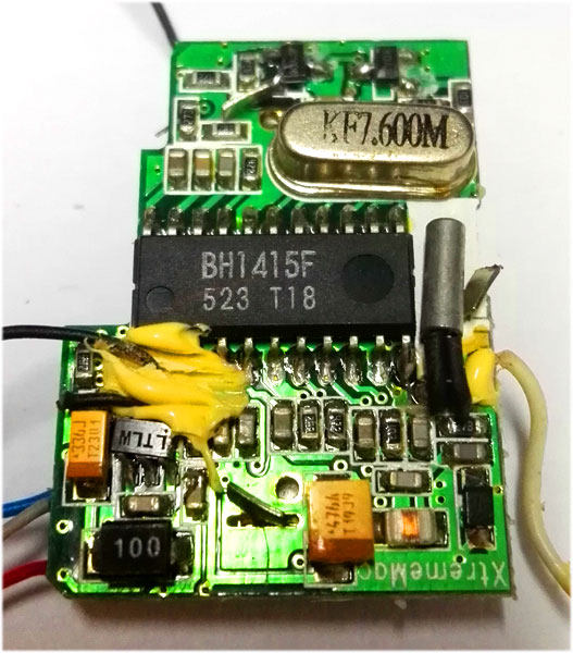
The FM transmitting circuit adopts a phase-locked loop system with stable frequency. This part consists of a high-frequency oscillator, a high-frequency amplifier and a phase-locked loop frequency synthesizer. The frequency modulation is realized by a high-frequency oscillator composed of a variable capacitance diode. The high-frequency oscillator is a phase-locked loop VCO through which the stereo composite signal is directly frequency-modulated. The high-frequency oscillator is composed of the LC loop outside the 9th pin and the internal circuit. The oscillation signal is output from the 11 pin through the high-frequency amplifier, and is sent to the phase-locked loop circuit for comparison, and then a signal is output from the 7th pin. Correct the value of the high-frequency oscillator to ensure stable frequency. Once the frequency set by the phase-locked loop is exceeded, the 7th pin will pull the output level high; if it is lower than the set frequency, it will pull the output level low; at the same time, its level will remain unchanged .
1) Integrate pre-emphasis circuit, limiter circuit, and low-pass filter circuit (LPF), so that the quality of the audio signal is greatly improved than that of discrete component circuits (such as BA1404, NJM2035, etc.).
2) The use of phase-locked loop frequency lock, and integration with the frequency modulation transmitter circuit, so that the transmitted frequency is very stable.
3) A 4-bit code switch is used for frequency setting, and 14 frequency points can be set, which is very convenient to use.
The internal structure of BH1417 is shown in Figure 1. It consists of 5 parts: audio preprocessing circuit (emphasis, limiting and low-pass filtering); fundamental frequency generating circuit (crystal oscillator, frequency division); phase-locked loop circuit (phase detection, frequency-locking); frequency setting circuit (high and low Level conversion); FM transmitter circuit. The peripheral circuits mainly include a frequency control circuit composed of a code switch, a carrier generating circuit composed of a voltage-controlled oscillator, a timer, and some coupling capacitors.
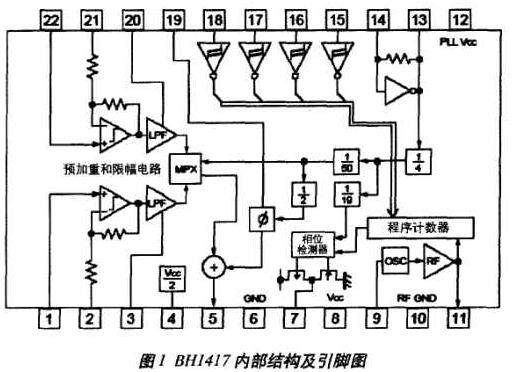
The stereo signal is input through pins 1, 22, and the external resistance-capacitance combination of pins 2, 3, 20, and 21 is used to complete the low-pass filtering, pre-emphasis and modulation of the stereo signal. The modulated composite signal passes through the 5 pin Output. After the frequency codes input by pins 15, 16, 17, and 18 are decoded and phase discriminated, pin 7 outputs the control signal VCO of the PLL oscillator. This VCO controls an external high-frequency oscillator circuit composed of discrete components to generate an FM frequency-modulated carrier signal, and performs FM frequency modulation on the composite stereo signal output from pin 5 through a Darlington transistor 2SD2142. The modulated signal is input to the BH1417 through pin 9 and the RF signal amplified by the internal RF amplifier is output from pin 11. The output signal can be directly connected to the transmitting antenna for transmission, or input to a radio frequency power amplifier for amplification and then transmitted to expand the transmission distance. 13 and 14 pins need to be connected with a 7.6MHz crystal oscillator to provide the stable clock required by the BH1417 internal phase discrimination, stereo signal modulation and other parts.